Total hunter OIC-1 ,OIC-2 installation instructions.

“SAFETY FIRST” STOP AND THINK!
Always make sure your firearm is unloaded and made safe before proceeding to work on it, remove bolt and magazine from the rifle.
PART #
OIC1 Lithgow, Rem700, Tikka short actions, CZ457-22LR and more
Year
05/06/2023
OIC-2 24/05/2024

Step#1: Remove the existing M5 button head screws holding the current KRG forend in place this will revel the KRG back bone on where the barrelled action is mounted to,
Step#2 Total Hunter recommends that you install all accessories on the forend M-loc side rails or bottom before mount the forend back onto the chassis to help aid in accessory positions, the M-loc’s are however accessible after installation as the back bone helps support the M-loc nuts to stay in position of where the back bone is present but it is noted that screws for the M-loc nuts siting in the insets must be checked so that they don’t interfere with the KRG back bone once tightened to stop deformation of the Forend and damage to the KRG back bone this can be archived with a simple mock up of the accessories and try fitting the forend to the KRG back bone for clearance and for a smooth fit it should slip over the back bone with a nice snug fit.
Step#4 Place an empty magazine into the selected magazine well and adjust the forend back until desired spacing has been altered for an effortless insert and removal of the magazine you may need to slightly tighten up one screw to help hold the forend in place while performing this action, if you have two magazines its noted that one may be a little different depending on manufacture specs and brands and they should all be tested to find a happy medium before torquing up the 6 M5 socket head stainless steel bolts to spec’
NOTE: Plastic 10 round MDT magazines will require a little modification on the grip ribs to allow the magazine to fit home all the way down in the barricade stop and click in the poly mags are also slightly over size to he steel magazines and will require a little bit of sanding on the outsides of the mags to get a better fit to the OIC-2 inlets, its recommend that after a fit has been acquired to fill the magazine( BOLT REMOVED) with 10 rounds and trial fit it again as the magazines as they tend to bulge a little with rounds inserted, We have done out best to cater to all 10round magazine types but due to the variants we have opted to measure the inserts of the most commonily used AICS steel magazines,
No loctite is to be used on these bolts they rely on dry torque settings, it is noted that there will be adjustable spacing gap at the front of where the back bone meets the OIC-2 on top this has been designed into the forend to allow and extra adjustments of the OIC-2 forend with out bottoming out on the front KRG back bone.
Step#3 After all M-loc screws have been adjusted to fit requirements the forend is ready to install on to the back bone with the barrelled action in the chassis, slide the forend over the back bone until is butts up against the rear handgrip panels of the rear stock and insert the six M5 stainless steal bolts provided through the forend , line them up with the back bone holes and loosely tighten so there is still adjustability back and forth in the forend there should be about 3mm worth of movement back and forth this will allow you to Set the forend to your magazine for fine tuning, SUB ARCA weight must be free floating in the forend if you have one installed, if the grub screws have been fixed in place to the back bone T-slot weight this will not allow you to adjust the wag well properly, loosen the grub screw so they are flush with the weight that can be done with a visual thought the M-loc slots,
Step#5 Now that everything is in the right position tighten up the 6 bolts to 42 lb-inch or 4.8 N-m in a cross hatch patten, out side first working your way to the centre bolts as last, “DO NOT OVER TIGHTEN SCREWS” they must be set to spec for optimum accuracy of the OIC-2 system. Your OIC-2- and rifle is now ready to be used and rifle zeroed out of experience if you are running a tuner / muzzle brake or the weight kits it is suggested to re zero your rifle while everything is in place to how you would normally run your rifle
Front cap torque screw settings are to be set at 24 lb-inch, If the speed screws are being used finger tight is sufficient for the duration of when being used in combination of the stage 1,2,3 weight kits for a PRS stage or balancing out the rifle, the speed screws can be a permanent solution to holding the front cap in place so they are available on demand if required by simply swapping out the top to bottom screws the speed screws can only be used on the top mounting holes when the cap is in use due to the screws being longer to hold the weight kit into place when the front cap is not in use to secure the weight kits in place,
NOTE: It is important to unsure correct alignment of the front cap to the weight system when the speed stage one weight kit has been installed, this can be done with a visual check to see if the holes are lined up before tightening the screws from the sides.

PART #
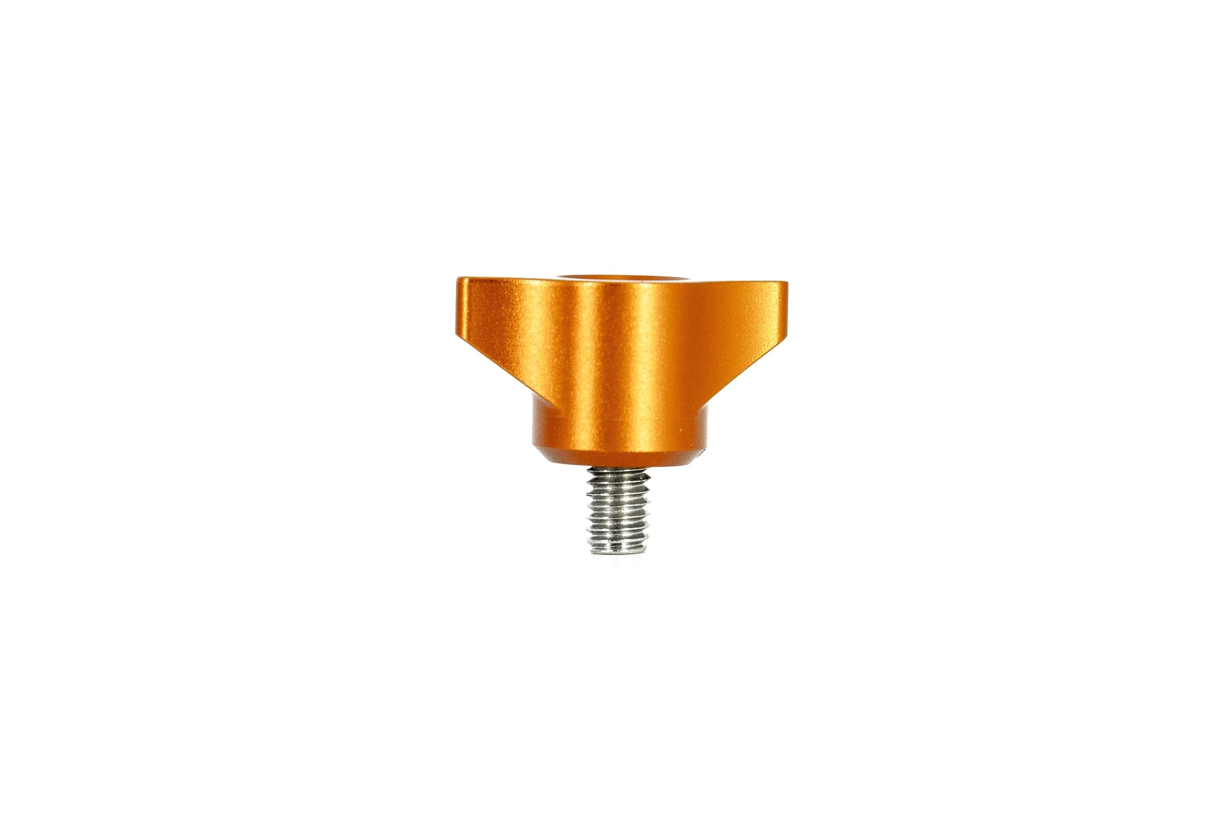
OIC-1 OIC-2 front cap/ M4 speed screws
Year
05/06/2023


STEP#1 Take the forend off the back bone to reveal the lower part of the chassis position the weight to match the holes that are drilled into the chassis backbone that holds the forend on insert the T-weight into the back bone and locate the alignment for the six bolt holes, its recommended that at least screws that hold on the forend are dummy fitted to ensure the gaps on the side of the bolts are even this will prevent and miss alignment issues one the forend is bolted into place.
STEP#2 The front of the T-slot weight should present itself flush with the front of the back bone, once alignment has been reached tighten the grub screws at 18 in-lbs in a cross hatch pattern.
NOTE: Do not over tighten the screws this can lead to excess damage of the back bone its it noted that it is normal for the internal area to mark due to the grub screws making resistance against the anodising of the back bone this is how it has been designed to ensure there is a solid contact and no rattle or movement under recoil with in the chassis under firing.
THIS PART WILL NOT WORK WITH THE KRG ENCLOSED FOREND, Due to the internal ribbing designed on the enclosed KRG product it will interfere with the total hunter weight,
PART#
GRAPPLERS GRIP, TACTOOTH M-loc
Year
05/06/2023
PART#
Extended night vision M-Loc bridge/barrel mirage cover (ENV)
OIC-2 now offers two models the Heavy Palma and M24 barrel profiles and now also a 1.25 straight profile
Year
05/06/2023
24/05/2024
PART #
Short Night vision Bridge/ M-loc (SNV)
Year
05/06/2023
24/05/2024
NOTE: short NVB have been designed to accept M24 and heavy Palma profiles 1.25 straight barrels will not be excepted with the short NV,
Step#1 With the forend mounted in position and locked into place as described in the OIC-2 manual instructions the Short night vision bridge is ready to install (SNV) with the use of the 8xM4 stainless steal screws torqued to 24 in-lbs ,Use a little bit of blue lock tight if this is a permeant fixed unit and position the SNV to suit your system the SNV has been designed to be able to utilise the KRG and Total Hunters screw hole profiles as they have been adopted on the OIC-2 to match the KRG and can be slid across both profiles to suit the users needs, The SNV has been developed for a 1inch barrel profile if unsure if this will fit your system please email us so we can assist you with the measurements, the SNV and be positioned in any direction to suit the desired look or to gain a little more length tot scope if needed.
NOTE: The short night vision bridge can be used as a quick day/night time running solution if the Night Vision scope is fixed to the unit and dismantled from the OIC-2 with the SNV still attached, Before removing the SNV It is recommend to mark the position of the SNV with the use of a permeant marker to the scope and OIC-2 so alignment can be achieved as close as possible when repositioning the system, a system zero check of the Night Vision optic recalibration is recommend if this has been done to ensure a correct Zero has been achieved. No loctite is required for this application,
PART #
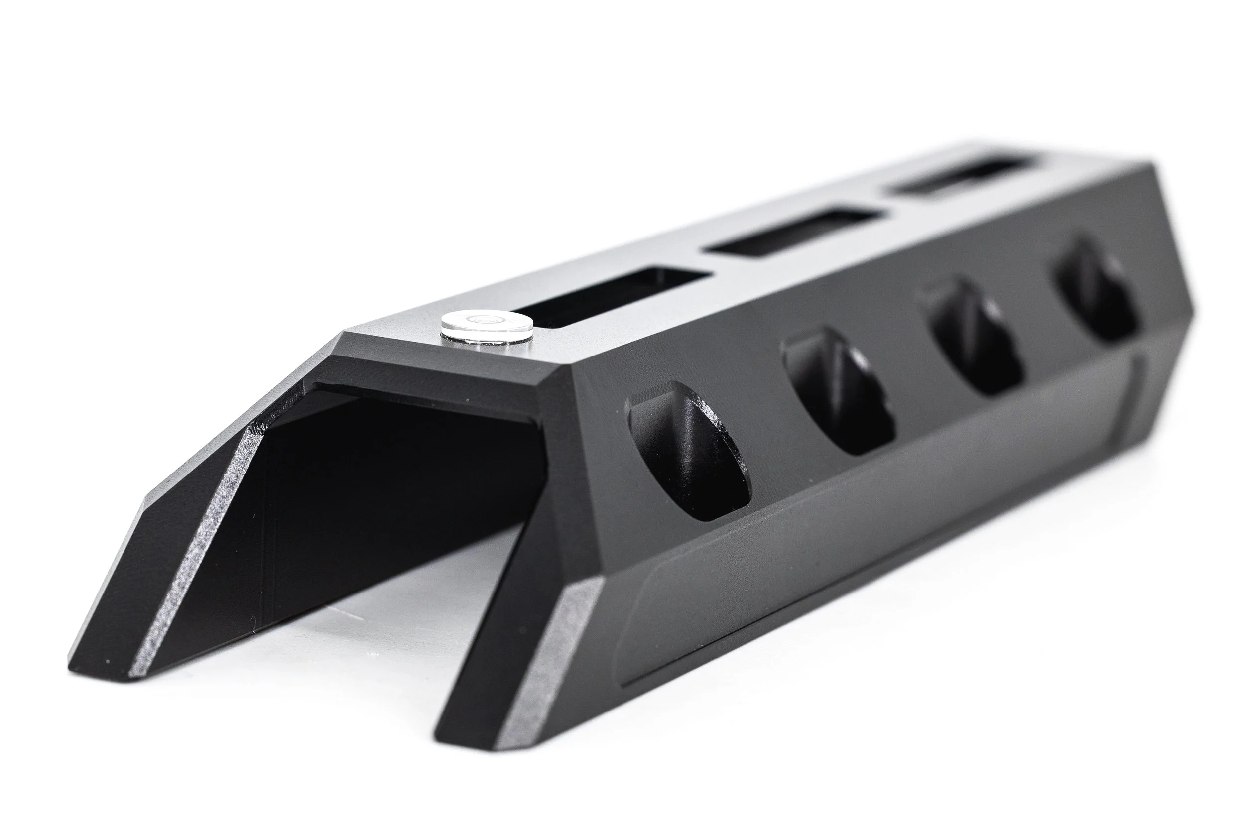
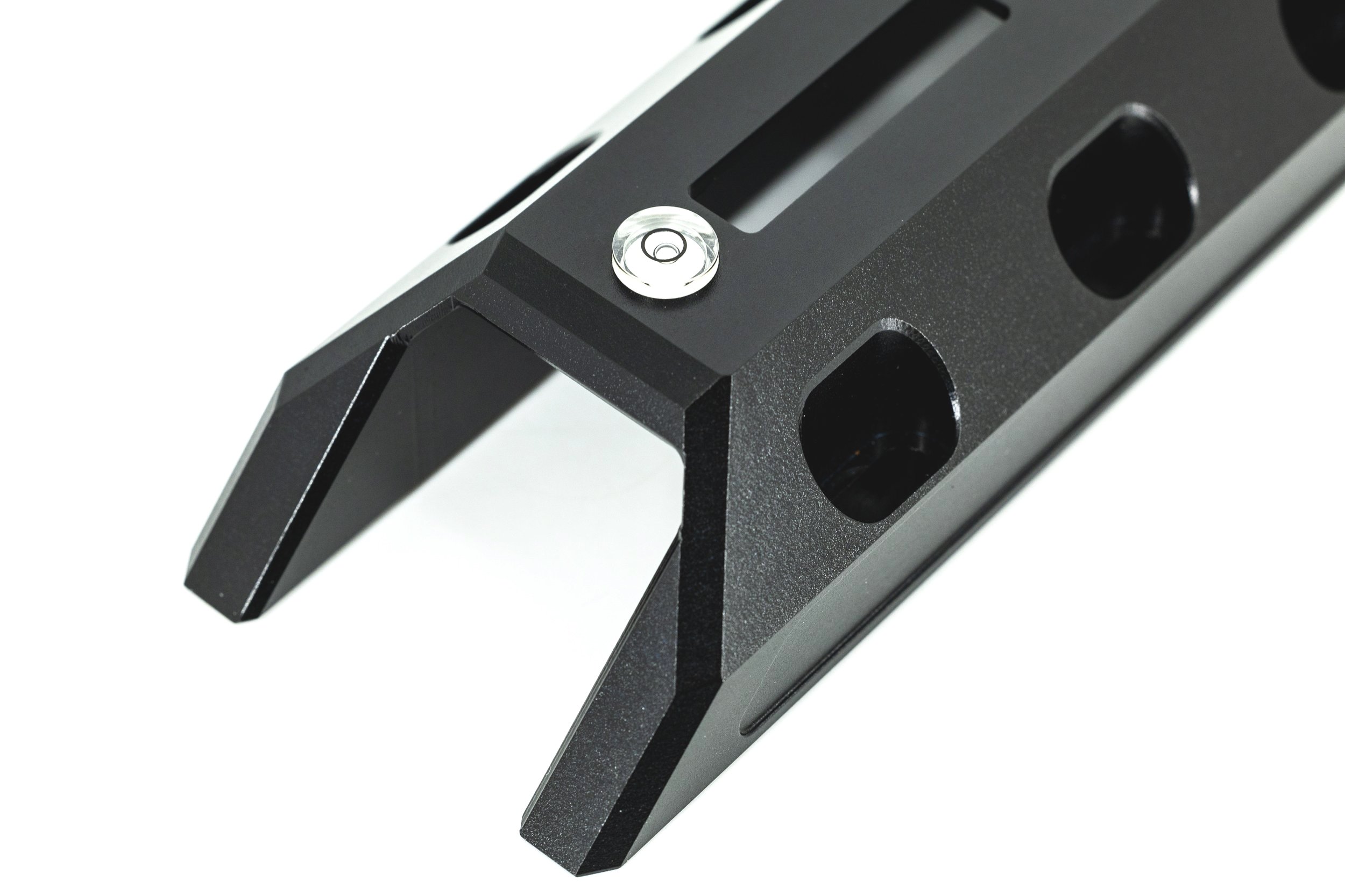
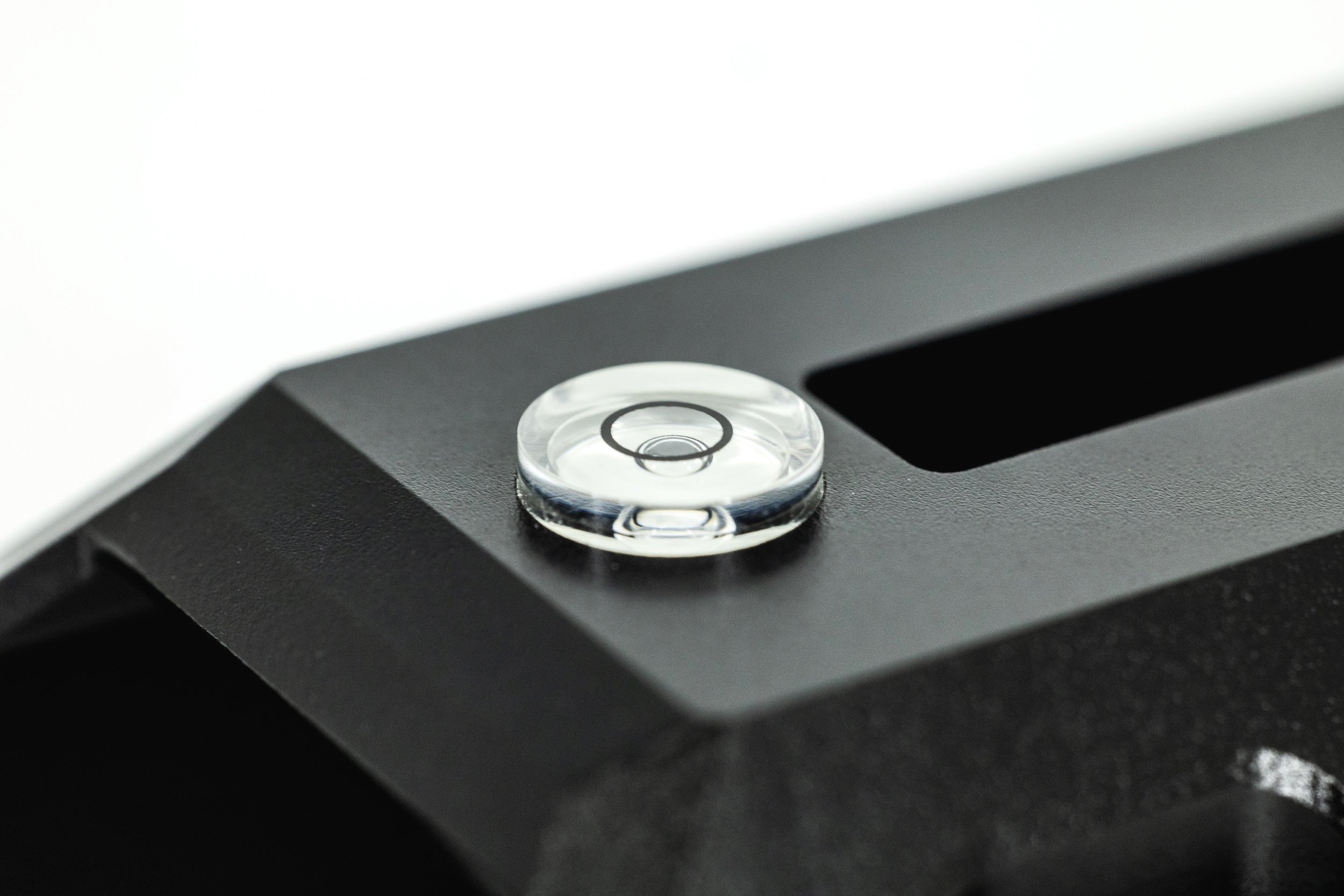
Alignment Bullseye Bubble DISCONTINUED
Year
05/06/2023
The bullseye bubble Is located on both the extended NV and Short NV bridges they are fixed into place to ensure that you can get a level rifle while mounting your NV and scope soloutions they are made out of marine grade scratch free acrylic and are extremely durable having a wide operating temperature range from -20 to + 70 degrees cellulose and are suitable for rugged use. Discontinued
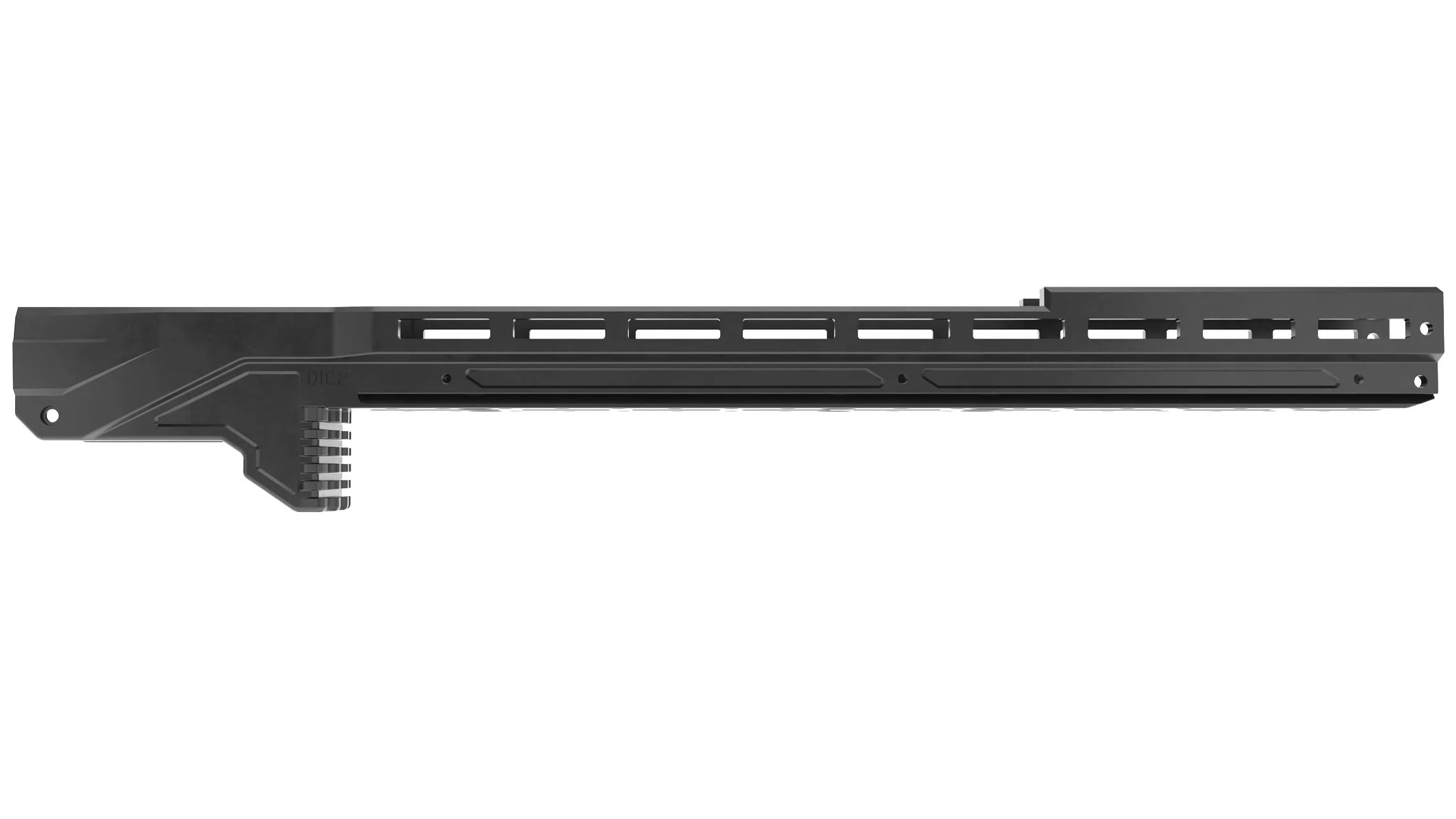
PART#
Interchangeable Magazine wells for the OIC-2
24/05/2024
Step#1 Interchangeable magazine wells have been developed to make the OIC-2 a multipurpose forend that is not limited to the one action expanding the use over any KRG whisky 3, X-Ray and bravo chassis in a variety of actions Center fire to Rimfire but simply swapping out the action specific magazine wells.
STEP#2 Mag wells come with centre locking countersunk screw torqued to 24 in-lbs located on the front internal section of the magazine well and two side screws torqued to 18 in-lbs that are located on the side of the forend NOTE!! magazine wells are a precise fit and its not recommended to paint the internal contact surfaces as this can lead to jamming of the the internal parts NO warranty’s will be issued if this is the case, it is recommended to lightly oil dry silicone lube (CRC 808) recommend for the contact surfaces of the magazine wells to aid in ease of release, Always make sure that the surfaces clean are clear of dirt and any debris, DO NOT FORCE THE PART HOME this will make the parts jam and will be difficult to remove them latter on.
STEP#3 Changing over to another magazine well action, take off the forend as listed above OIC-2 installation instructions, Access the magazine well loosen all screws the internal and external of the mag well, once all loss the magazine well should slide freely out the back of the forend if there is a little bit of resistance a slight bit of pressure can be applied to the top of the forend out wards which straddles the KRG back bone to help in assist freeing up the magwell, it is noted that all the parts are made out a one piece billet aluminium and will take a lot of force to bend the externals out of shape, the tapered internal AICS magazine profile lends its self to aid in removal of the Magwell if there is a problem encountered with a tight fit, if you have any concerns please email us for technical support so we can help resolve the issue.
PART#
OIC-2 side rails
24/05/2024
STEP#1 Place the side rails on the location inserts that have been machined into he the OIC-2 on the inside surface of the rail there is a mirrored profile to match that of the forend, Once location is found lightly screw into position starting from he centre and then the out sides L/H and R/H once centred and the rails look in position tighten the screws to 24 In-lbs.
Take note - if using the internal weights to make sure that you have placed the short screw at the front of the forend so that the screw thread dose not interfere with the internal weight slide channel if you have a weight front cassette kit installed remove the front cap including the weights to make sure that the screw thread is not pushing on the side of the internal weights and hindering the quick realise function.
All care has been taken to make sure all the screws have been sized and supplied for the intended purpose please check you have the right screws inplace before fixing all the parts together to prevent damage to the parts.
PART#
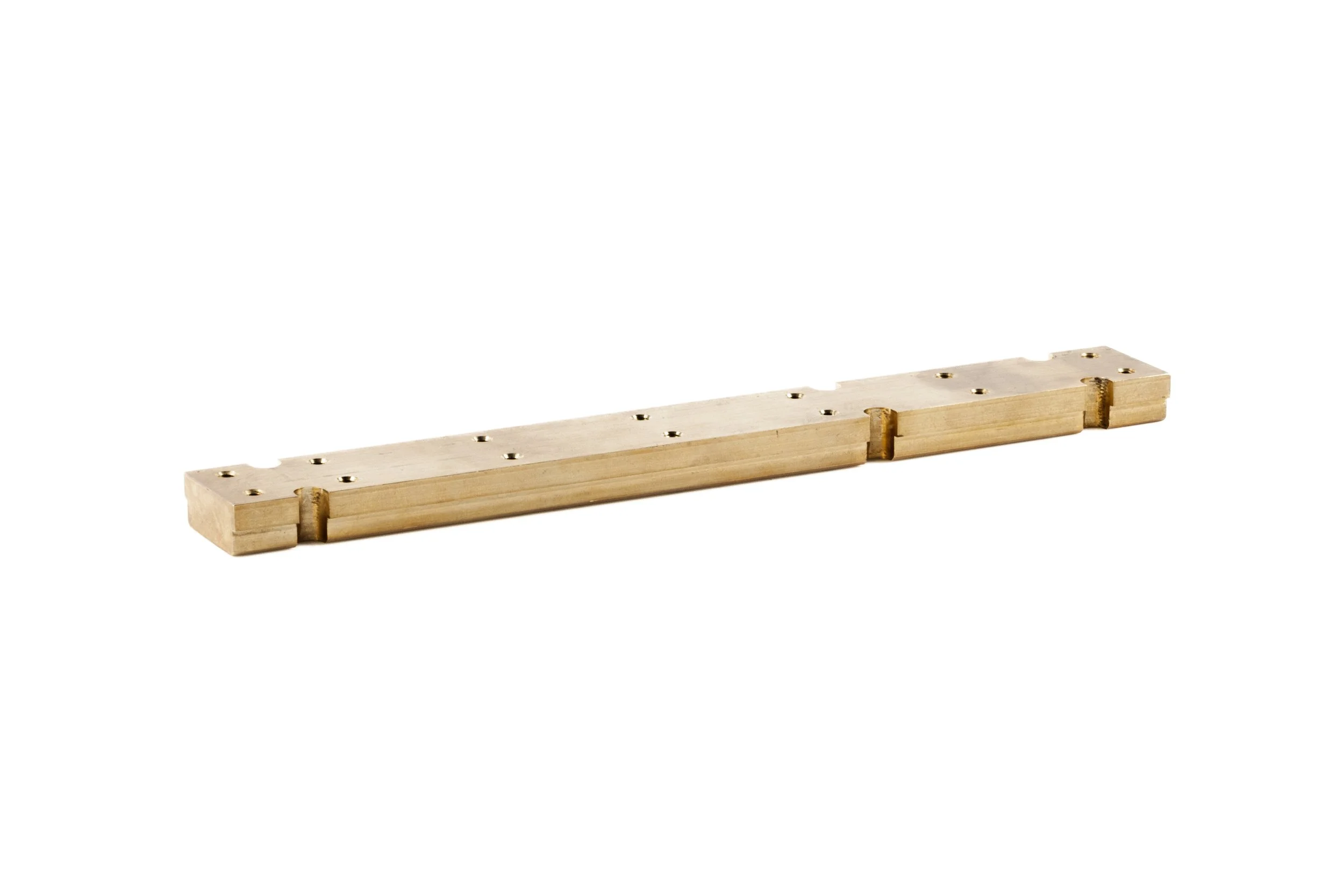
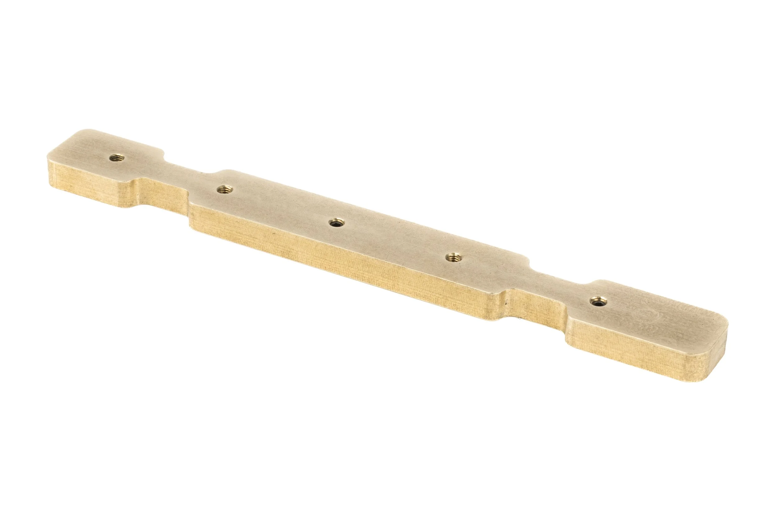
Extended extra heavy backbone T-slot weight
#1 :510g - 18oz
24/05/2024
PART#
Front solid brass internal cassette weights stacks stages 1,2,3
stage #1 :300gr - 10.6oz
stage #2 :245gr - 8.6oz
stage #3 :310gr - 10oz
24/05/2024
STEP#1 Remove the 4 screws holding the front cap on to the forend. Depending on the stage kits purchased it good to dummy fit all the kits together first fit the front cap to the stage #1
This stage must be fitted first as it has the key slots to hold all the weights together and prevents them from floating around inside the chassis there is a location slot for the front cap to slot where the stage #1 will fit into loosely place two screw into the side of the forend to hold the front cap in place this will prevent the weights from sliding out the front of the chassis while trial handling and finding the correct balance point for the desired barrelled action its going onto weights can be adjusted to suit by adding or subtracting the stages.
STEP#2 It is noted that the stage #1 base weight is the foundations for other staged weight kits however stage #3 can be swapped around with if needed, they can be used in a different configuration its is noted that stage #2 will not fit ontop of stage #3 if used in this configuration due to the interference with the top front cap inner mounting tabs.


PART#
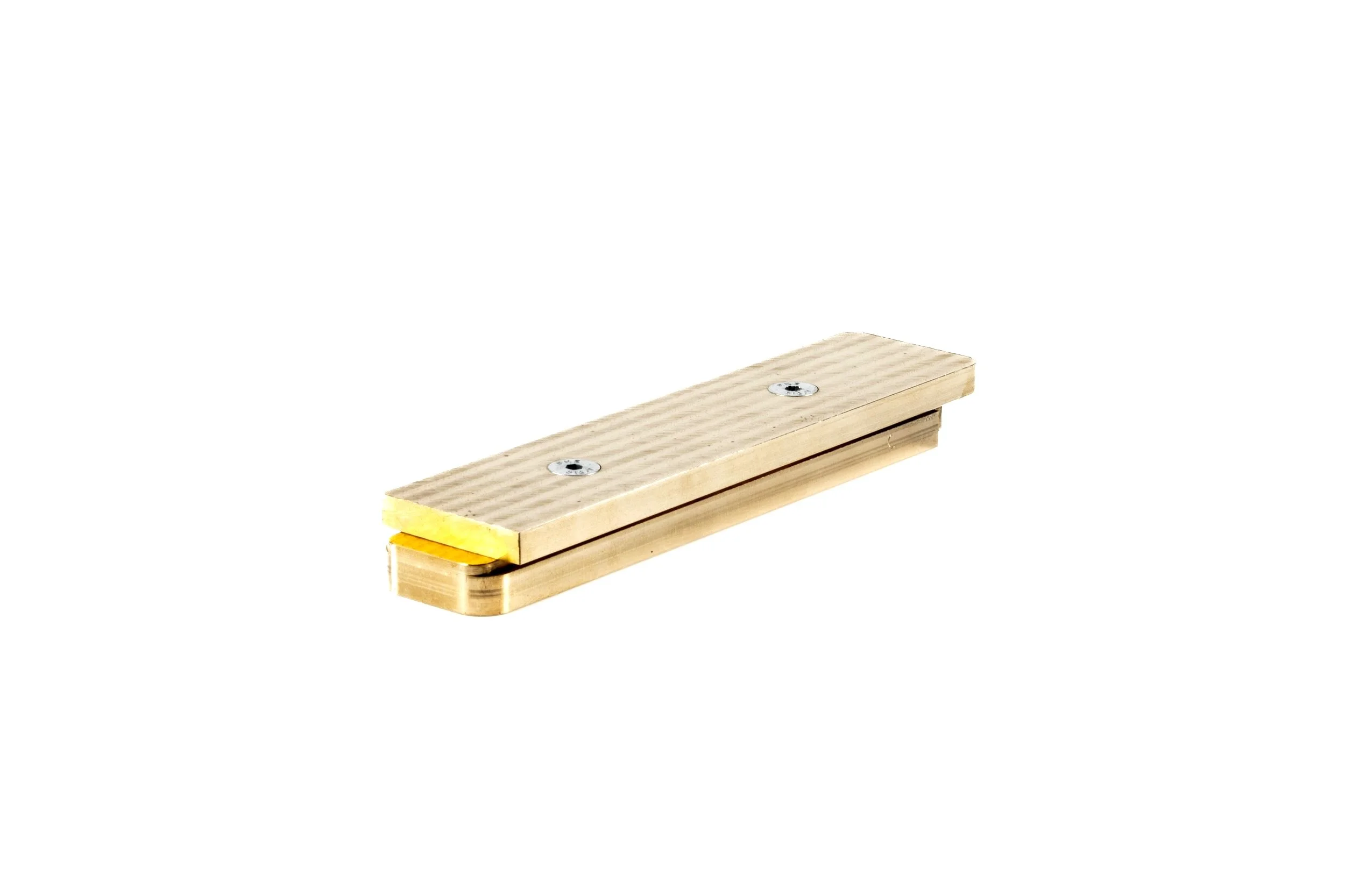
Sub internal Arca weight
24/05/2024
#1 :410gr - 14.4oz
Step #1 The sub Arca weight designed is to be in conjunction with the T-Slot weight, the sub Arca weight will centralise the weight to the balance point of your rifle, Remove the forend by loosening the 6 bolts and slide the forend of the KRG back bone, simply drop the weight into the machined out area of the internal of the forend the part has been machined so that I can only fit one way, once fitted take care to ensure you have the grub screw Allen head facing to the outside so these can be accessed though the M-loc once bolted together, hold the forend slightly angled downwards so the weight dose slip out of its locating position and slide the forend back into position along the back bone until home, fasten the forend bolts to spec, as listed above within accordance with the forend installation guide lines,
Step #2 With the forend now fixed into position and you are happy with the adjustment tighten the grub screws that can be accessed though the bottom of the M-loc holes until snug, the grub screws will hold the weight in position and stop any rattle Loctite is not recommend,
PART#
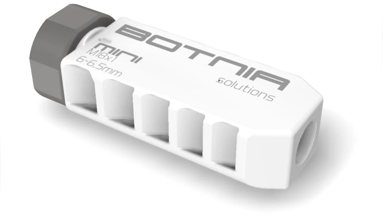
BOTNIA MUZZLE BRAKE
02/02/2025
Muzzle Brake Safety Instructions and Mounting Guidelines Mounting Instructions for the Muzzle Brake
STEP#1. Preparation Unload your firearm and ensure it is completely safe before proceeding with installation “SAFTEY FIRST”
STEP#2. Apply Lubricant: Apply a small amount of firearm-grade grease or lubricant to the threadson the barrel. This reduces friction and ensures smooth threading. Note: The muzzle brake is made of 316L steel, which is prone to cold welding if proper lubrication is not applied. Ensure sufficient lubricant is used to prevent this issue and facilitate easy removal in the future.“ALWAYS Inspect the barrel threads and muzzle brake threads to ensure they are clean and free from debris”.
STEP#3. Thread the Brake: Gently thread the muzzle brake onto the barrel by hand. It should turn freely without resistance. Do not use tools or excessive force during this step.
STEP#4 Alignment: Once the muzzle brake is fully threaded, check its alignment with the barrel. Ensure the ports are oriented correctly according to your desired setup. Position one bubble level on the muzzle brake and one on the scope base or cap to help with precise indexing and alignment.
STEP#5. Secure the Brake: Use the self-timing nut to secure the muzzle brake in place. Tighten the nut to achieve proper alignment and secure the brake. While the brake nut is designed to withstand high torque, it is recommended not to exceed 30 Nm. Over time, carbon buildup can increase the break-of torque, making removal more difficult if overtightened.
STEP#6. Final Check: Confirm the brake is securely attached and properly aligned. Check for any obstructions in the bore or ports before using the firearm.
Safety Instructions for Using the Muzzle Brake
The following safety instructions are crucial for ensuring safe operation when using your muzzle brake:
Compatibility Check: Ensure that the muzzle brake is designed for the same caliber as your rifle. Mismatched calibers can result in severe damage to the firearm and may cause injury.
Alignment Verification: Always verify that the muzzle brake is properly aligned before firing. Misalignment can cause dangerous malfunctions.
Inspect Regularly: Periodically inspect the muzzle brake and firearm to ensure the device remains securely attached and in good condition. Check for signs of wear, damage, or corrosion.
Be Aware of Blast Direction: Muzzle brakes redirect gas to reduce recoil. Always be mindful of the blast direction, especially when shooting near others.
Use Protective Equipment:
“Always wear appropriate eye and ear protection when firing your firearm”.
Be aware that debris from carbon buildup can exit the brake along with the gas at any point during the brake's lifetime. Maintain a safe shooting environment to mitigate any potential risks.
Follow Firearm Safety Protocols: Always follow the manufacturer’s safety instructions for your firearm, including proper maintenance, handling, and operation practices.
Do Not Modify: Do not modify the muzzle brake or attempt to use it with firearms for which it was not designed.
Consult a Professional: If you encounter any issues during use or suspect improper installation, consult a qualified gunsmith or contact our support team for assistance.
Limitation of Liability
Botnia Solutions and its vendor’s does not accept responsibility for any misuse, improper installation, or failure to follow the instructions provided with this product. Users assume all risks associated with the use of the muzzle brake, including but not limited to damage to the firearm, personal injury, or property damage. By using this product, by purchasing you agree that it is your responsibly and adhere to all safety guidelines.
Total Hunter is not responsible for fitting of this device all users accept liability when purchasing this product and is used at own risk the purchaser takes all accountability ensuring the correct applications and safety guid lines are followed for use of this accessory , see FAQ on T&C
For additional questions or support, please contact us at Info@botniasolutions.com.
Step#1 With the OIC-1 OIC-2 forend in place and every thing has been checked to ensure the the forend is located in the desired place the ENV (extended night vision) cover can now be placed onto of the forend, position the ENV to line up with the desired holes and check to make sure that the barrel has cleared the front of the bridge and it is not interfering with the free float there should be a minimal .5 mm gap dividing the ENV to the top of barrel the ENV has been developed for a 1inch barrel profile, Heavy Palma and M24 barrel profiles anything above this could see interference with the barrel and the NV bridge, The 1.25 ENV only utilises the side M-locs due to the barrel width interfering with the top screw hole locations attache the ENV like you would any other side M-loc system.
Step#2 Once clearance has been checked the user can now insert the M-loc nuts into the positioned area where the back of the ENV straddles over the side M-loc rails the ENV bridge tabs are now over the M-loc Nuts and the screws can be inserted loosely to hold the ENV in place, always check screw lengths so that they don’t bottom out on the KRG back bone, it is advised that a small amount of blue lock tight is to be used on the M-loc screws to prevent them vibrating lose under recoil.
Step#3 Slide the ENV bridge to line up with the Front cap to ensure alignment, once alignment has been achieved the screws can be fixed into place in a cross hatch pattern booth the top screws and the side M-loc screw are to be set at 24 in-lbs with a sparing amount of blue lock tight, Your Extended NV bridge is now ready for use, the 1.25 profile is to be mounted as listed above in step #1
NOTE: If the user is planing on fixing a night vision clip on or scope to the ENV it is best to mock up the units up on the ENV first with the help of either the M-loc slots provided or using an picitinniy rail to suit for an solid mount, all care has been taken to ensure that the lowest hight has been achieved possible with he ENV, it is up to the user to ensure that the night vision system will fit there rifle barrel profile along with scope ring/picitinniy hight’s as there’s to many variants to account for with every rifle, If unsure email us so we can assist in finding a solution to your system.
Step#1 The GRAPPLERS GRIP and TACTOOTH have be specifically designed for the OIC-1 , OIC-2 and are compatible with (MDT,MPA,KRG,Ect: as long as they have M-loc slots) they come supplied with the needed bolts and M-locs the torque setting is 24lb-inch and its recommended that a small amount of blue lock tight is to be applied to the thread and left for 10mins or to dry before tightening the screws, this helps the M-loc Cam into the M-loc slot and lock I into place.
STEP#2 Position the Grappers/TACTOOTH thumb stops while the rifle is placed on a bag this step is made easier if you have someone to help assist you so they can move the thumb stops and make note of the M-loc spacing ,place your hand on the middle of the bag next to your rifle rail so that the bottom three fingers are able to grab the front of the bag nice and firm now tilt your hand slightly forward so that your thumb sits somewhat horizontally in line look to the side of your rifle and count the M-locs to where you feel is a good position on your rifle, mount the thumb stops to engage your thumb or where your feel has the most comfort for you position.
STEP#3 Before tightening the thumb stops or accessories ALWAYS MAKE SURE TO TRY FIT! screws can vary along with M-loc spacings, fit the M-locs to the OIC1 first to ensure there is clearance from the back bone to stop the end of the screws bottoming out on the Back bone which can and will cause damage to both products, the screw end should sit flush with the M-loc Nut once tightened if unsure it is suggested that the OIC1 forend is unscrewed from the KRG back bone and the part try fitted to ensure that there is clearance to the KRG chassis back bone.
NOTE: The TACTOOTH displays and aggressive tooth patten that has been designed to engage into Barricades it is up to the user to insure the proper safety precautions are maintained whilst handling firearms.